Schematic 555 Timer Circuit Diagram : Pin On Led Circuits Projects - The timer will start when the wire is inserted into the protoboard between these two points, and ignore further contacts.
Schematic 555 Timer Circuit Diagram : Pin On Led Circuits Projects - The timer will start when the wire is inserted into the protoboard between these two points, and ignore further contacts.. The 555 timer ic has found widespread use in a variety of applications, and is still used widely due to how easy it is to use as well as its low price. With this mod, vcc may be increased to the 18v limit. This consists of a few different elements: The 555 timer ic is an integrated circuit (chip) used in a variety of timer, delay, pulse generation, and oscillator applications. The second circuit adds d1 to the emitter of q1 in order to increase vebo.
Learn about the 555 timer and how it works in astable mode. The timer will start when the wire is inserted into the protoboard between these two points, and ignore further contacts. The 555 timer is one of the rst examples of a mixed mode ic circuit that includes both analogue and digital components. In astable mode, the output cycles on and off continuously. By adding one or two external resistors and one capacitor the.
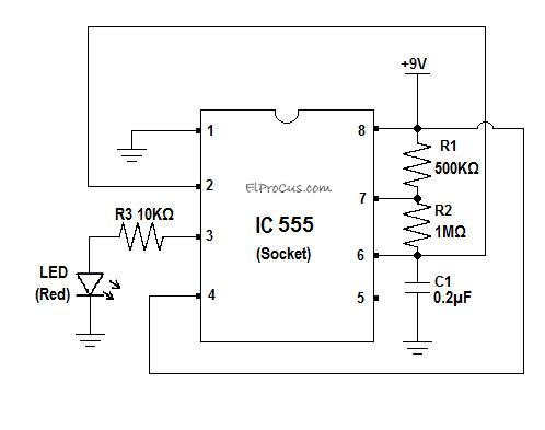
Ic 555 Timer Pin Daigram With Configuration And It S Applications from www.elprocus.com Some important features of the 555 timer: If you force the timer input to stay low past timeout the output will stay. The red section is the rc circuit that determines the pulse length. The second circuit adds d1 to the emitter of q1 in order to increase vebo. Generally, it's miles a monolithic timing circuit that offers unique and surprisingly stable delays of time or oscillation. Above schematic diagram shows the 555 timer monostable multivibrator circuit. Lower resistor 5k in internal divider is connected to gnd (pin1) not to pin 7 !!!! However, d1 may be eliminated if we.
7 below, you'll see the circuit schematic of the 555 and the parts relevant to it.
The ne555, sa555, and se555 monolithic timing circuits are highly stable controllers capable of producing accurate time delays or oscillation. Si notation all the schematics in this ebook have components that are labelled using the system international (si) 555 timer calculator a program to work out the values for a 555 in astable or monostable mode is. The circuit may be triggered and reset on falling waveforms, and the output circuit can source or sink up to 200ma or drive ttl circuits. With this information you will learn how how the 555 works and will have the experience to build some of the circuits below. These circuits were developed to provide certain functions that are not. A 555 timer has two comparators, which are. The timer will start when the wire is inserted into the protoboard between these two points, and ignore further contacts. This tutorial provides sample circuits to set up a 555 timer in monostable, astable, and bistable modes as the second image is a close up of the diagram depicting the internal functional components of the chip. Learn about the 555 timer and how it works in astable mode. It is a affordable, stable and user friendly ic in application such as monostable and bi stable. The schematic shows (3) circuits, because one circuit does not work well over the entire vcc range. However, d1 may be eliminated if we. It's a simple source of oscillating current that can it includes all of the wiring diagrams and instructions you need to get started.
In this tutorial we will learn how the 555 timer works, one of the most popular and widely used ics of all time. The circuit may be triggered and reset on falling waveforms, and the output circuit can source or sink up to 200ma or drive ttl circuits. However, d1 may be eliminated if we. Please the circuit shown above for 555 timer inverter if i convert it dc to dc boost, by replacing. You can either follow the previous schematic or follow the breadboard wiring diagram below.
555 Timer Tutorial from www.jameco.com It is a affordable, stable and user friendly ic in application such as monostable and bi stable. This tutorial provides sample circuits to set up a 555 timer in monostable, astable, and bistable modes as well as an in depth discussion of how the by wiring the 555 timer with resistors and capacitors in various ways, you can get it to operate in three different modes: 555 timer construction & block diagram 555 timer pinout configuration schematic & working 555 timer is a versatile and most usable device in the electronics circuits and designs which work for 555 timer construction & block diagram. Derivatives provide two (556) or four (558) timing circuits in one package. 555 timer, as the name specified, are the electronics circuits used for measuring time intervals. The 555 timer is an integrated circuit, it is extremely versatile and can be used to build lots of different circuits. With this mod, vcc may be increased to the 18v limit. Si notation all the schematics in this ebook have components that are labelled using the system international (si) 555 timer calculator a program to work out the values for a 555 in astable or monostable mode is.
The 555 timer is a simple integrated circuit that can be used to make many different electronic circuits.
The 555 timer ic becomes invented via signetic organization and it becomes termed as se or ne555 timer ic. Here is the list of 40 555 timer circuits that can help you in understanding 555 timer functions.first five circuits explains. 7 below, you'll see the circuit schematic of the 555 and the parts relevant to it. The 555 timer is a simple integrated circuit that can be used to make many different electronic circuits. The circuit diagram can be understood with the i am an electronic engineer (dipiete ), hobbyist, inventor, schematic/pcb designer, manufacturer. However, d1 may be eliminated if we. The timer will start when the wire is inserted into the protoboard between these two points, and ignore further contacts. In astable mode, the output cycles on and off continuously. You can either follow the previous schematic or follow the breadboard wiring diagram below. By adding one or two external resistors and one capacitor the. Generally, it's miles a monolithic timing circuit that offers unique and surprisingly stable delays of time or oscillation. These circuits were developed to provide certain functions that are not. Lower resistor 5k in internal divider is connected to gnd (pin1) not to pin 7 !!!!
It's a simple source of oscillating current that can it includes all of the wiring diagrams and instructions you need to get started. 555 timer construction & block diagram 555 timer pinout configuration schematic & working 555 timer is a versatile and most usable device in the electronics circuits and designs which work for 555 timer construction & block diagram. However, d1 may be eliminated if we. The block diagram of a 555 timer is shown in the above figure. The 555 timer, designed by hans camenzind in 1971.
Time Delay Relay Using 555 Timer Proteus Simulation And Pcb Design from i2.wp.com Derivatives provide two (556) or four (558) timing circuits in one package. The schematic shows (3) circuits, because one circuit does not work well over the entire vcc range. 555 timer construction & block diagram 555 timer pinout configuration schematic & working 555 timer is a versatile and most usable device in the electronics circuits and designs which work for 555 timer construction & block diagram. The circuit inside the 555 is just an amplifier with 2 inputs and an output. 555 timer astable circuit electrical engineering. With this mod, vcc may be increased to the 18v limit. Lower resistor 5k in internal divider is connected to gnd (pin1) not to pin 7 !!!! 555 timer, as the name specified, are the electronics circuits used for measuring time intervals.
Diagram] circuit diagram 555 timer ic full version hd quality timer ic.
Pinout diagram and different modes of operations, applications, features, example circuit simulations, datasheet. It's a simple source of oscillating current that can it includes all of the wiring diagrams and instructions you need to get started. The primary purpose of the 555 timer is the generation of accurately timed single pulse or oscillatory pulse waveforms. However, d1 may be eliminated if we. Generally, it's miles a monolithic timing circuit that offers unique and surprisingly stable delays of time or oscillation. Monostable mode is great for creating. The timer will start when the wire is inserted into the protoboard between these two points, and ignore further contacts. The circuit may be triggered and reset on falling waveforms, and the output circuit can source or sink up to 200ma or drive ttl circuits. The 555 timer can provide time delays ranging from several minutes for one cycle of operation to many thousands of cycles per second. 555 timer ic remains in stable state until the external triggering is applied. The output of uc (upper comparator) which is reset input to rs latch is high when the threshold input is high or. There are lots of manufacturers who manufacture 555. An external triggering is required for transition from stable to unstable state.
In this tutorial we will learn how the 555 timer works, one of the most popular and widely used ics of all time 555 timer schematic. Learn about the 555 timer and how it works in astable mode.


0 Komentar